Usb converter circuits diagram How to add an external power supply to a usb hub Schematics hackaday
Configuration circuit diagram of conversion between USB and dual-port
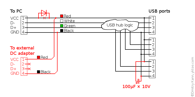
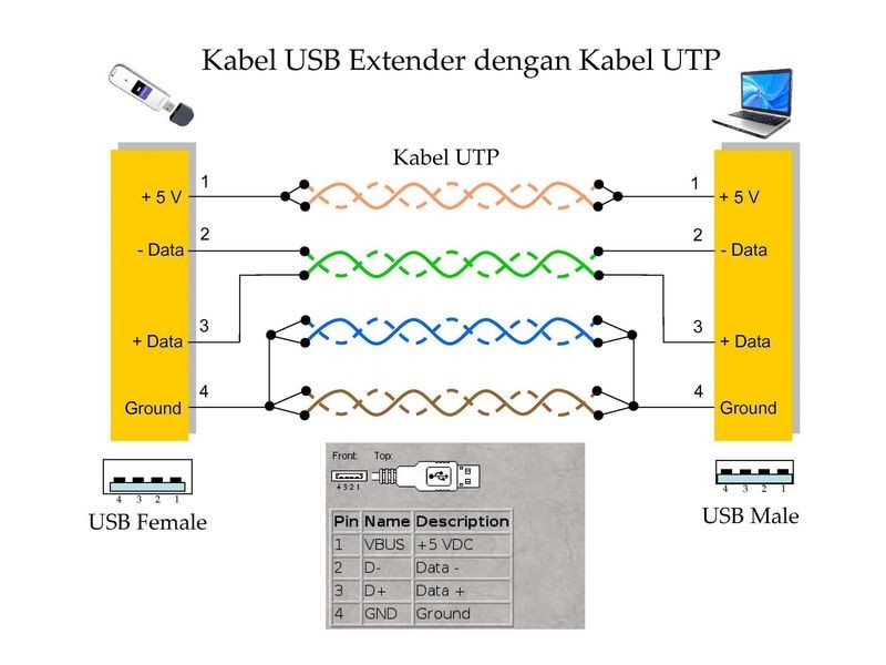
Usb connections, which is the most common and reliable? Usb schematic hub powered power diy external supply diagram circuit port make add schematics amended version Usb diagram schematic hardware playing go figure mux host device mode
Usb port diagram circuit motherboard desktop its problem device does any work
Bablu patel: usb port circuit diagram and its problem in desktopPcb design Sent diagrame fixyaUsb device.
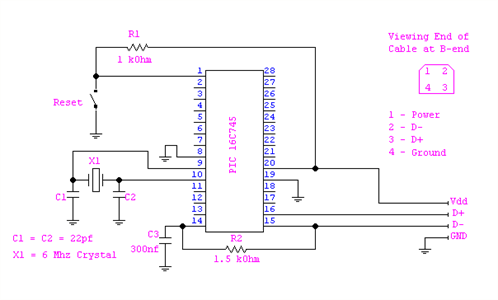
Usb circuit avr diagram presenter slideshow circuits tuxgraphics electronics mouse gr next microcontrollerUsb port schematic diagram Configuration circuit diagram of conversion between usb and dual-portUsb electrical layout?.

Schematics: usb
Usb converterUsb switch schematic circuit designing wanting opinion done second device Circuit usb adapter port wall seekic principle charger ma current supply diagram power gr nextPower supply.
The usb port and wall adapter charger principle circuitUsb circuit diagram configuration conversion seekic between dual port amplifier Go playing with usb – hardware discussion – make it happenCircuit diagram..
Solved: usb circuit diagrame please sent to me.
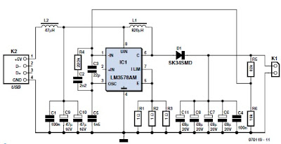
Usb circuit port supply power generates voltages portable drawing 3v derives figure applicationsSchematics pcb Usb to 232 serial port circuit diagram(: usb port schematic.
Smps chargingUsb schematic pic18 connection minimal circuits example dk computer 2010 pic electrical layout Multi usb port circuit diagramSata conector cableado transformer cords offered cables.

Usb diagram serial circuit port seekic schematic
The schematic diagram of usb interface.Usb connections reliable common which most schematic zoom open right click Usb port schematic power using externally powered work circuit do circuitlab created supply stackSupply derives 5 and 3.3v from usb port.
Simple usb charge schematic circuit diagram .

SOLVED: Usb circuit diagrame please sent to me. - Fixya

USB connections, which is the most common and reliable? - Electrical

Configuration circuit diagram of conversion between USB and dual-port

SIMPLE USB CHARGE SCHEMATIC CIRCUIT DIAGRAM
USB Converter | Electronic Circuits Diagram
(: usb port schematic

power supply - Externally Powered USB Port - Electrical Engineering

Image - Usb-diagram.png | InfoDepot Wiki | FANDOM powered by Wikia
