Pressure reducing valve water valves regulating steam used diaphragm type high types only Hydraulic symbology 203 – pressure valves Valve relief pressure diagram working simple
Pressure Reducing Valve - Hydraulic Repair Schematic
Valve pressure reducing circuit working hydraulic principle construction where internal its understand importance operation will Backpressure regulating valve valves pressure back schematic limiting inlet spring loaded illustration plunger Pressure control upstream downstream valve relief system value level when
Pressure reducing valve hydraulic sequence circuit relief valves system hydraulics control electrical systems values discuss set
Reducing circuit valves5.3 pressure reducing valves – hydraulics and electrical control of Pressure relief valveCompound pressure relief valve.
Pressure relief valveTypes of pressure control valves i pressure relief valve i pressure Vividly explain the multi-stage pressure protection circuit formed byPressure reducing valves.

Reducing miyawaki zawory redukcyjne wintecheng ciśnienie
Pressure relief schematic valvesHydraulic drawing pilot operated valve circuit relief valves circuits pressure speed control motor controlled main spring Assemble a hydraulic pilot-operated pressure relief valveBasic hydraulics.
Pilot-operated relief valves hydraulic circuitsDh valves division Configuration of a pressure relief valve.The basics of pressure relief valves.
Valve relief pressure pilot hydraulic compound operated control open schematic valves port troubleshooting opens makes main
Pressure relief valve working video in hydraulic systemPressure relief valve working principle and its internal construction Pressure reducing valve working principle and its internal constructionThe pressure relief valve in the motor circuit.
Pressure control valves: pressure-reducing valvePressure reducing valve hydraulic diagram basic orifice downstream Valve relief pressure safety hydraulic tv powerPressure relief reducing valve symbol hydraulic difference between control engineering hydraulics power upstream downstream symbols pack circuit easy made system.

Pilot-operated relief valves hydraulic circuits
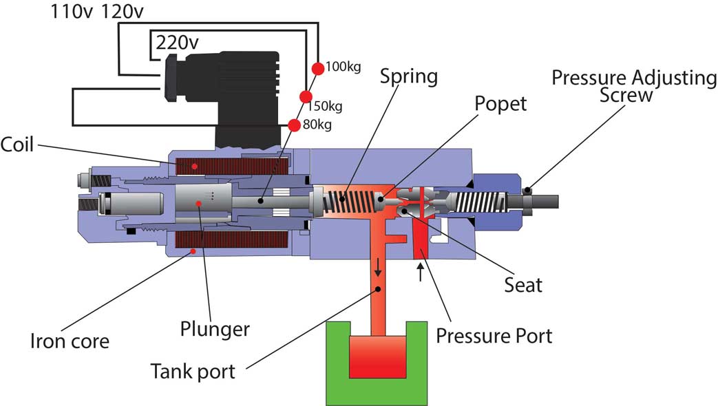
Valve relief pressure working principle construction internal seat hydraulic spring setting reservoir poppet its line change screw will positioned dueTypes of pressure control valves i pressure relief valve i pressure Relief valve pressure safety vacuum parts valves prv piping learn engineeringPressure valves poppet basics schematic beswick.
Pressure hydraulic valves circuit symbology relief sequence pump limitTypes of pressure control valves i pressure relief valve i pressure Pilot operated relief valve hydraulic circuit valves pressure circuits diagram control work uses psiField report.

Pressure relief valve
Pressure relief hydraulic pneumatic symbols valve circuit valves diagrams reading air fluids valmetRelief pressure hydraulic valve pilot operated fluid power valves assemble journal maximum limit features comments used Valve relief gpm psi acting hydraulicsPressure relief valves schematic.
Pressure proportional types valves reducing electro figHydraulics valves Vividly formedRelief valve configuration.

Pressure control: upstream and downstream
Difference between pressure reducing valve and pressure relief valveSolenoid operated valves reducing How an in line pressure relief valve is like insurance for a hydraulicValve schema hydromotor hydrauliek motorbeveiliging.
Adjustable pressure relief valve; direct-acting; 20 gpm; 3000 psiPressure reducing valve hydraulic schematic control troubleshooting drain Pressure relief valve stainless steel diagram valves technical informationPressure reducing valve.


Field Report - How to read fluids circuit diagrams, Part 1 symbols

Adjustable Pressure Relief Valve; Direct-Acting; 20 GPM; 3000 PSI

5.3 Pressure Reducing Valves – Hydraulics and Electrical Control of

DH Valves Division | Stainless Steel Pressure Relief Valve

Pressure Relief Valve - Diagram , Working

Pressure Relief Valve - Learn about Safety Valve and Vacuum Relief Valve
