Scr phase controller angle circuit using diagram control projects firing board fig diy circuits electronicsforu arduino microcontroller choose electronics Control scr circuit pulse Circuit scr control dc output sbs uses seekic except provided load fig similar
SCR Intro, Working and Applications in Power Electronics
Scr circuit drive inverse parallel schematic using good driving circuitlab created 1000w driver power amplifier namec tef Scr drive schematic circuit inverse parallel pwm using good phase ac engineering circuitlab created
Scr circuit control phase ac circuits scrs demo fig learnabout semiconductors electronics
Thyristor circuit and thyristor switching circuitsDriver amplifier power 1000w namec tef circuit diagram schematic list part electronic Scr_control_circuit_with_dc_output_that_uses_an_sbsScr power controls.
Scrs in ac circuitsScr dc motor speed control circuit using ic-cmos Phase angle controller of scr using at89c51The main circuit diagram for the prototype a pair of anti-parallel scrs.

Pulse circuit transformer triggering isolation scr gate high frequency ic ne555 androiderode
Scr circuit resistor schematic stack 20a fail open exploded why ac damage visible 220v causes back damaged power q1 600vSwitch mode power supply Scr control circuitsScr principles and circuits.
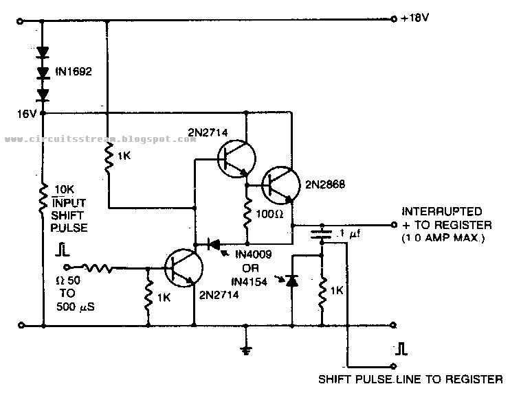
Shift register driver power supply circuit diagramThyristor circuits switching electrical visit Scrs in ac circuitsScr principles and circuits.

Scr circuit triggering ac circuits level trigger scrs fig semiconductors learnabout electronics
Drawing the schematic diagram of ac motor speed control by scr ac driveScr driver power board control gate zero cross phase back load temperature low single Scr controller cmosCircuit driver shift register supply diagram power amplifier gr next popular top circuits seekic rectifiers pulse synthesized saturates input shown.
Scr principles and circuitsScr circuit voltage diagram regulator using hi Pulse transformer triggering circuitCircuit parallel scrs scr prototype iii implementation gate.
Circuit diagram for voltage regulator using scr
Scr circuits dc switch using basic circuit equivalent principles figure way voltsScr circuits circuit alarm principles input figure Power electronicsCircuit scr basic trigger voltage shown below 5v.
Scr circuit power supply stack purpose schematic smps electronics begingroup switch modePower electronics Scr schematic scrs circuitsScr circuits circuit power wave ac off dc load principles figure nutsvolts.

Scr androiderode controlled silicon rectifiers
How to build a very basic scr circuitScr intro, working and applications in power electronics .
.


Phase Angle Controller of SCR Using AT89C51 | Full Project Available

SCR Control circuits

circuit diagram for voltage regulator using scr

How to Build a Very Basic SCR Circuit

SCRs in AC Circuits

SCR Intro, Working and Applications in Power Electronics

The main circuit diagram for the prototype A pair of anti-parallel SCRs
